The Bacterial Flagellum - Figures
Figure 1. Locations of flagellar parts (e.g., rod), their component proteins (e.g., FlgB, FlgC, FlgF & FlgG), and their functions (e.g., drive shaft).
Figure 1. Locations of flagellar parts (e.g., rod), their component proteins (e.g., FlgB, FlgC, FlgF & FlgG), and their functions (e.g., drive shaft).
 (48k)
(48k)
 (56k)
(56k) (80k)
(80k)
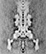
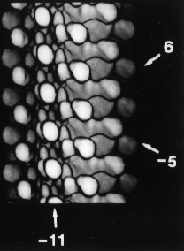
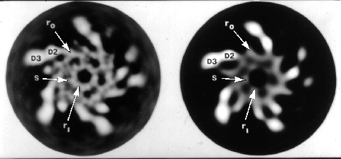
Figure 2. Images of flagellar parts obtained by electron cryomicroscopy and image analysis.
A) A section through the three-dimensional map of the flagellar motor. The y-shaped feature on the lower left and right sides correspond to the C-ring, which is about 450 Å in diameter.
B) Surface view of the flagellar filament (propeller). The numbered arrows point to the main helical ridges. This mutant propeller lacks a corkscrew shape, which is essential for function but makes structural studies difficult.
C) A transverse section through the filament with the domains marked. D3 corresponds to the outer knobs seen in image B. D2 denotes the stubby features behind the knobs. Ri and Ro mark the inner and outer cylindrical domains, which we believe are made of alpha helices. The lumen of the inner cylinder, which we think is the subunit-export channel, is 30 Å in diameter.